Basic Robotics - Make Robot with Raspberry Pi | Web Controls
This robot is not just a remote controlled toy. The aim here is to make robot / platform which can be progressively scaled up to perform variety of robotic experiments. These experiments will include:-
- Integrating sensors, camera, speaker and other hardware with robot.
- Playing with advanced web technologies to interact with sensors of a smart phone through browser and using them to control the robot.
- Running Machine Learning Models and venturing into the realm of Artificial Intelligence.
- And many more.
These experiments will be covered in upcoming articles one by one. As of now, let's get started and make robot with basic components that can be controlled through a simple Web Application.
The unique aspect of this robot is that it requires a single battery bank to provide power to all the components.
Generally, such robots are built with 2 power sources, one 5 V DC source for single board computer / microcontroller and the other 12 V DC source for DC motors. In this robot, a low cost DC to DC up conveter has been used to convert 5 V DC output of a power bank to 12 V. This obviates the requirement of additional power source and helps in saving space and minimising hardware clutter.
Make Robot: Hardware Components
The components used are tabulated below. You can click on the component name to see the source of purchase.
| Mechanical | Electronics |
| Metallic Robotic Chassis | Raspberry Pi 3A+ |
| DC Motor - 100 RPM, 12 V | L293D Motor Driver Module |
| Robotic Wheels | MT 3608 (DC - DC up converter) |
| Acrylic top cover | Battery Bank with 2 USB slots |
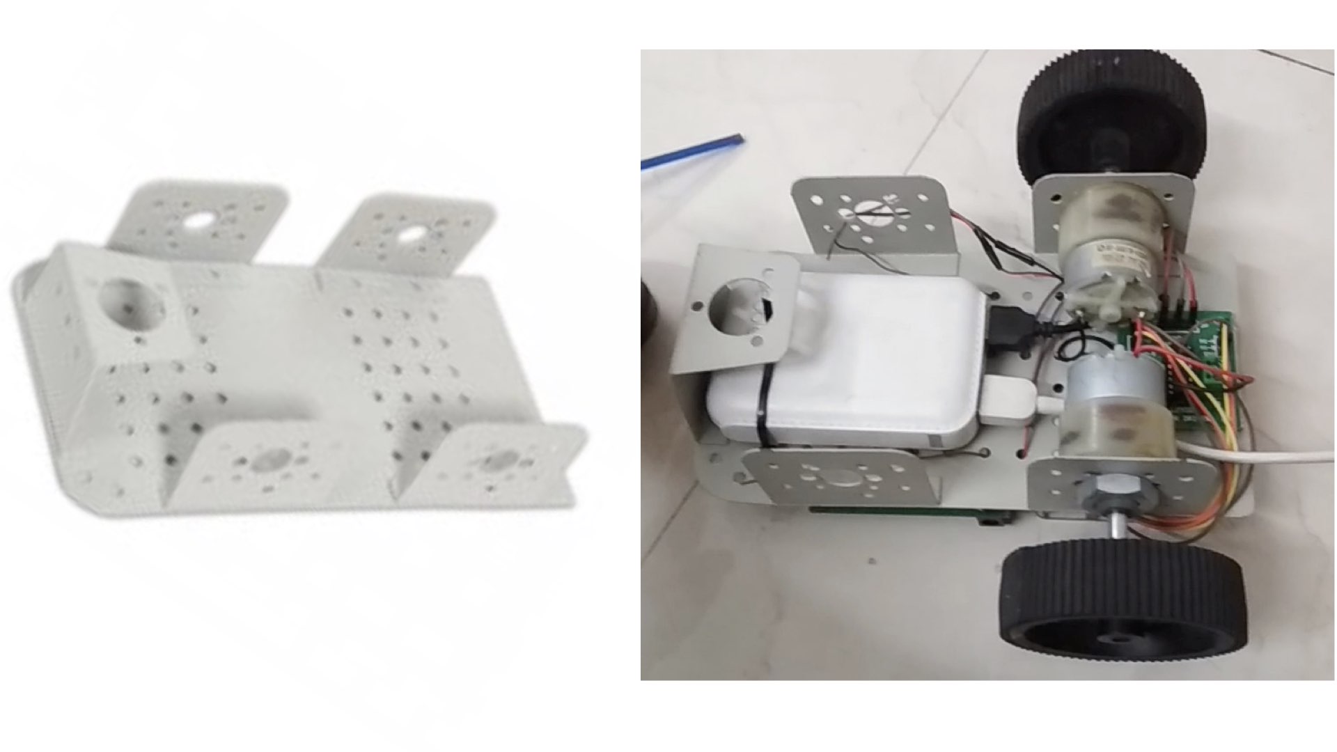
Robot Chassis
Select a strong & compact chassis to mount the components. A large number of options are available on internet to choose from. The chassis used to build this robot is shown below
DC Motor - 100 RPM, 12 V
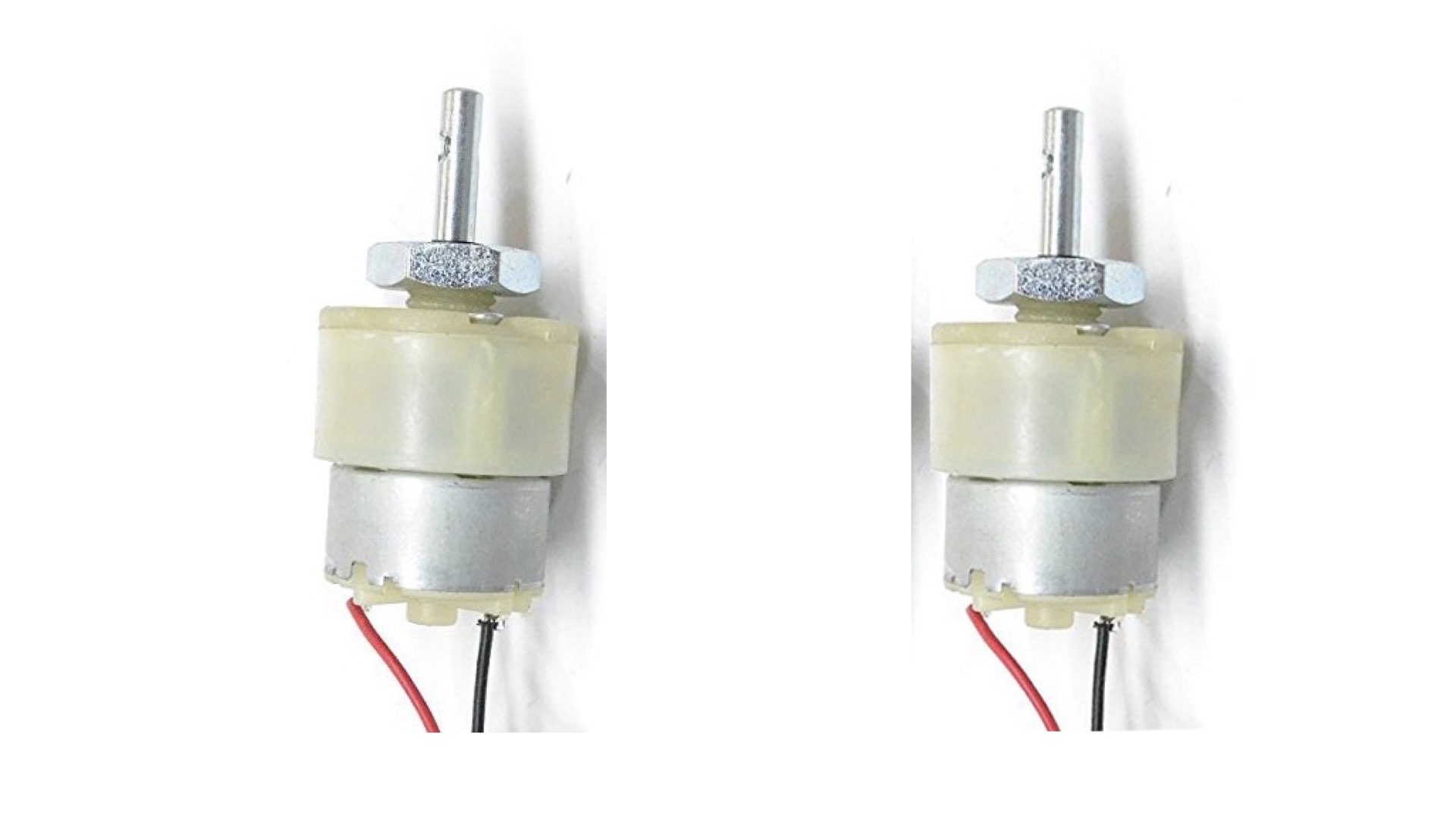
These are simple geared motors with a gearbox built into it. Such motors are used in variety of robotic applications. This motors has a 3 mm threaded drill hole in the middle of the shaft which allows it to connect to the wheels or any other mechanical assembly.
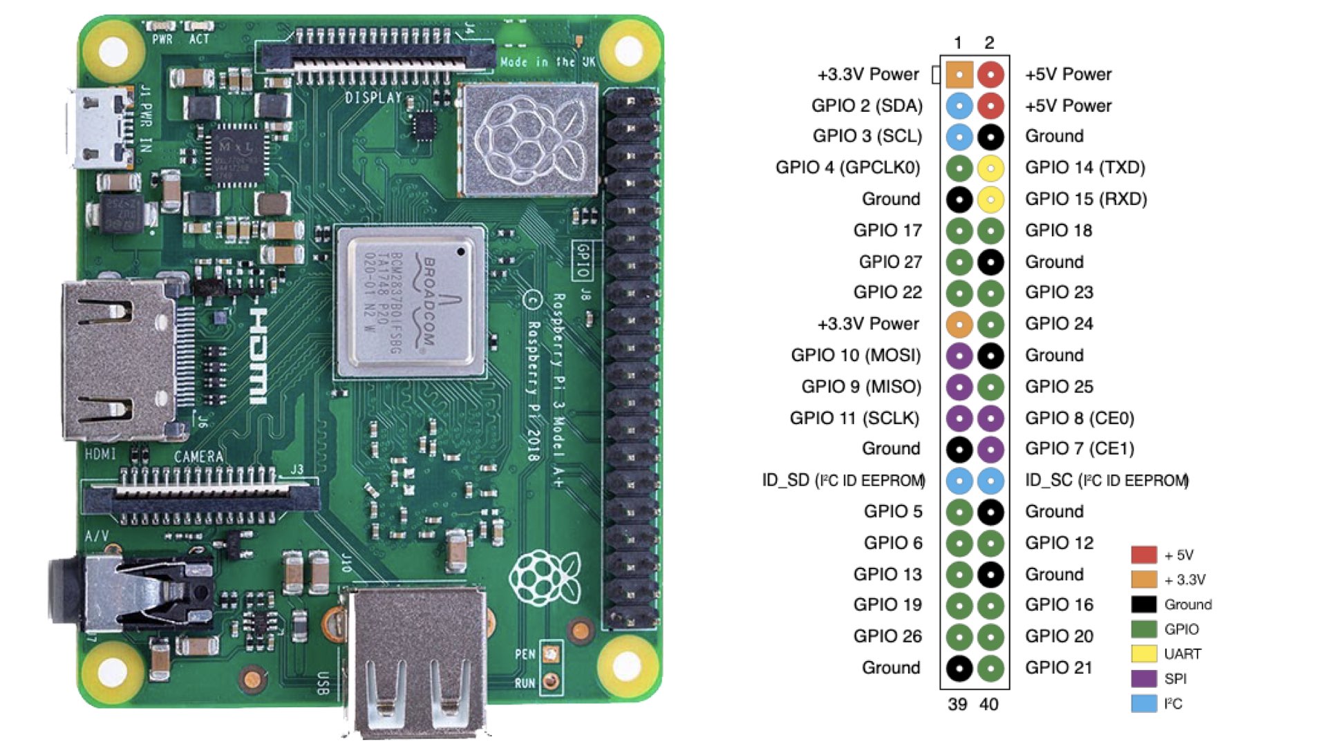
Raspberry Pi 3A+
This is the main processing element of the robot. Raspberry Pi comes in various models and form factors. This model has relatively small form factor and requires less power to operate as compared to other models. It requires 5 V to operate and can be powered up through a common battery bank. It has a 40 pin GPIO section which can be utilised to interface with external peripherals.
Battery Bank
While making a choice for the battery bank, the important factors to consider are its size, weight and mAH value. Choose the one which can pack maximum mAH in minimum size and has 02 ports.
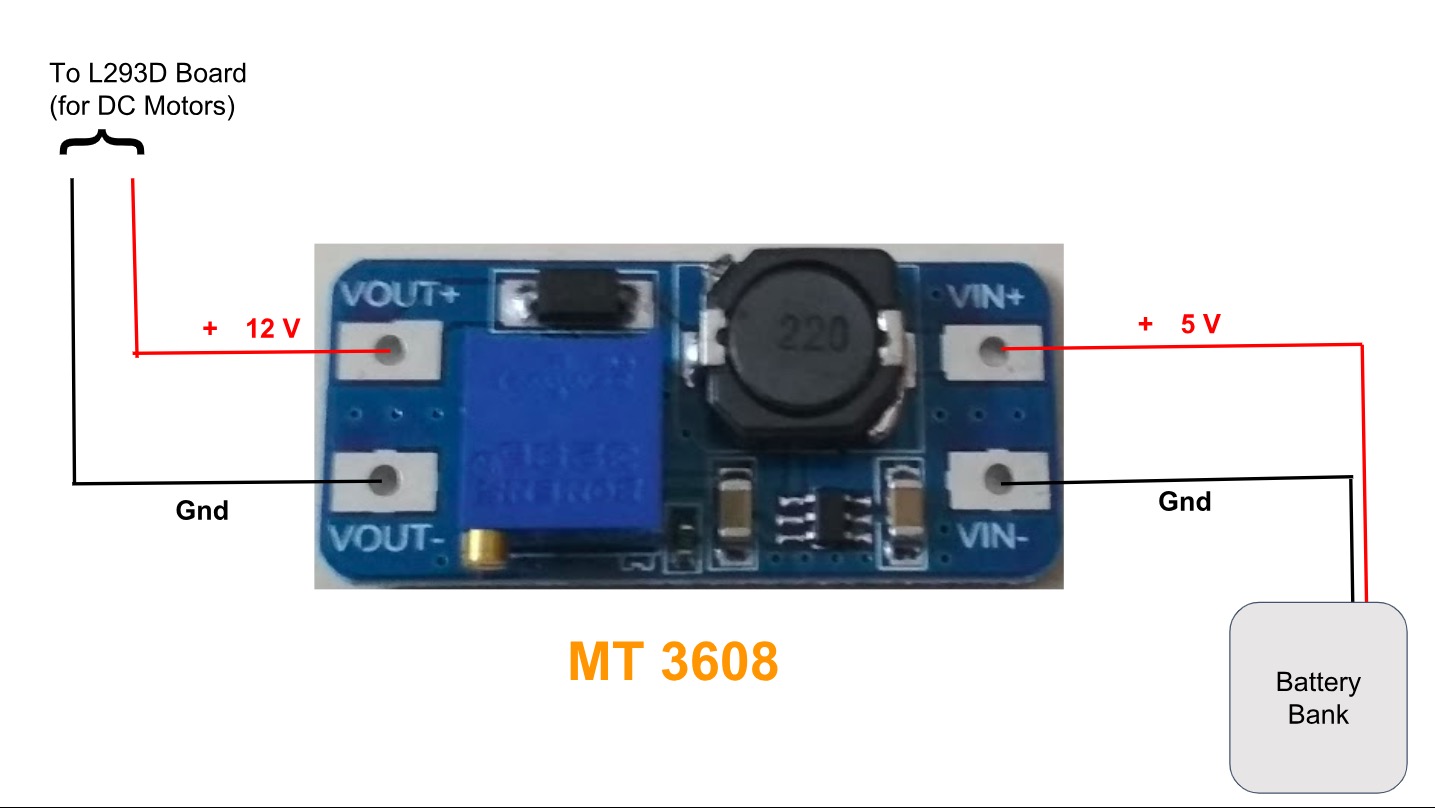
MT 3608
The MT3608 module is a low-cost DC-DC Step Up converter that can step-up a 2-24V input voltage up to a 5-28V output at up to 2A. To make robot, it is used to generate the 12 V DC supply required to drive the DC motors as shown below.
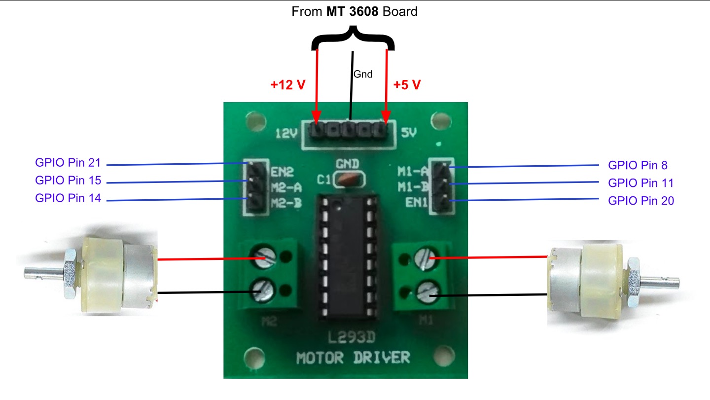
L293D Motor Driver Module
L293D Motor Driver Module is an expansion board of L293D IC. The board can drive upto 02 DC motors in both directions and at variable speeds. It can be interfaced with Raspberry Pi as shown below to make robot.
The direction of motor is controlled by switching the logic on M1 and M2 pins. Speed of the motors can be adjusted by providing a suitable PWM signal at EN pins.
Connection Diagram of the Robot
The components are connected as per the diagram shown below:-
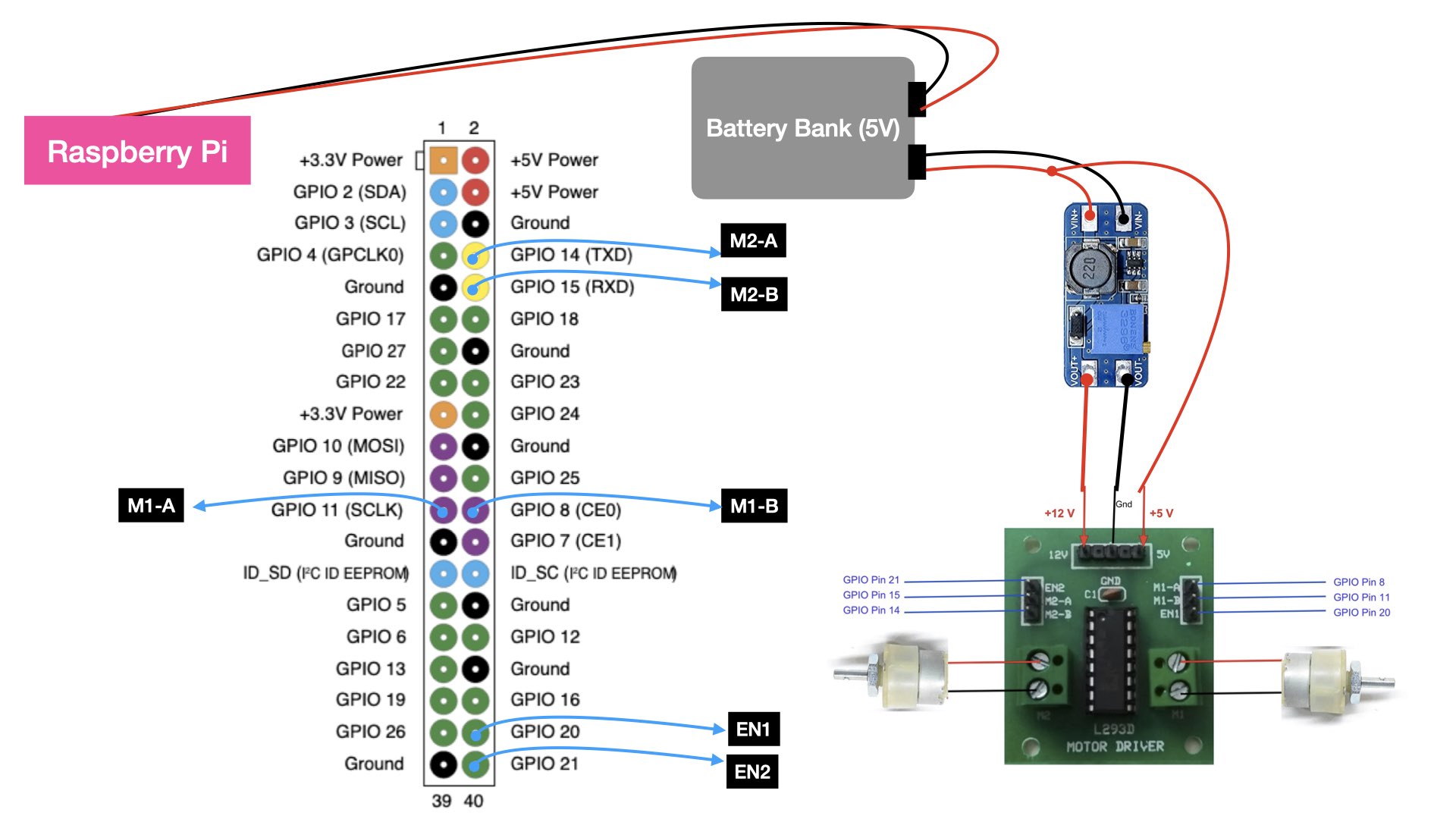
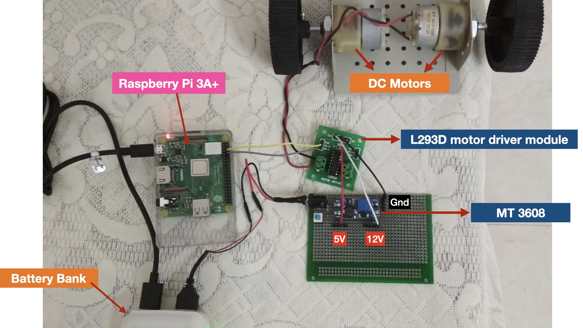
The robot assembly as per above diagram is shown below (only one motor is connected for demonstration).
Make Robot: Software Components
The code for this project is uploaded on github. Download and refer it to correlate with the explanation provided below.
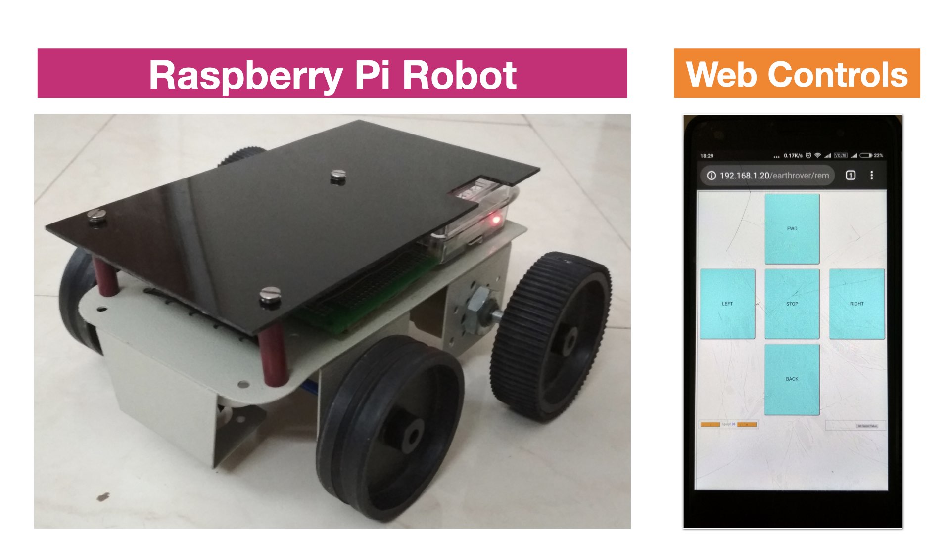
The GUI to control the robot is written in PHP, HTML & Javascript. The code is placed in the file 'remote.php' . Using a browser on mobile phone, you can type the URL to access this file as shown in the picture below.
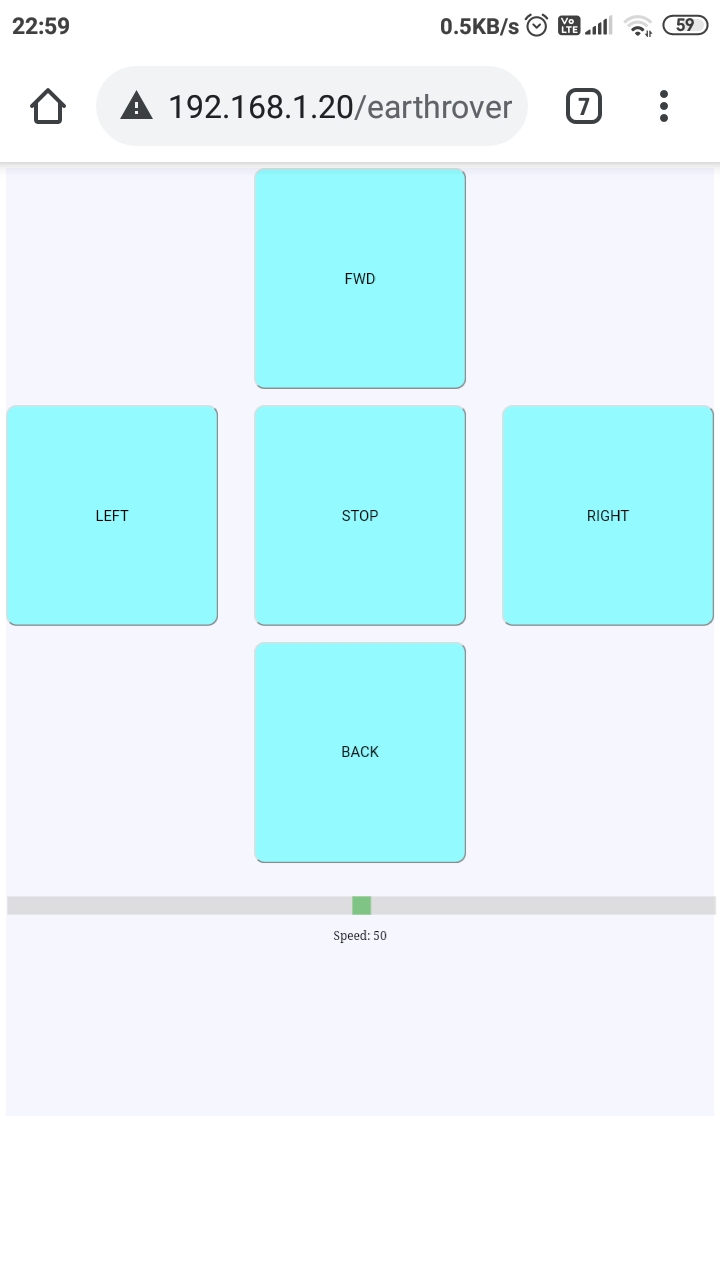
remote.php
The code of 'remote.php' begins with importing few files. The CSS file is responsible for look and feel of the GUI. The jquery file is used for client server communication via ajax. The file 'remote.js' implements the javascript functions that are invoked upon pressing buttons of the GUI.
<head>
   <title>Remote</title>
   <link href="css/remote.css" rel="stylesheet" type="text/css">
   <script src="js/jquery.min.js"></script>
   <script src="js/remote.js"></script>

</head>
The buttons and slider for speed are rendered using the HTML <input> tags. Each button has a respective 'onclick' javascript function associated with it, defined in 'remote.js' file.
remote.js (Client Side code)
When a direction button is pressed following function is invoked and a letter corresponding to the direction is passed as a variable to this function. This function simply sends the direction value to a php file (ajax_direction.php) in the server via background ajax call.
//---------DIRECTION---------------------------------
function button_direction(val)
{
    console.log("button val:" + val);

    $.post("ajax_direction.php",
     {
        direction: val
     }
    );
}
This file also has a function that senses the press arrow keys of a keyboard as show below. It invokes the 'button_direction()' function and passes the direction parameter corresponding to the arrow key.
$(document).keydown(function(e){
    if (e.keyCode == 37)
    	 button_direction('l');
    if (e.keyCode == 38)
        button_direction('f');
    if (e.keyCode == 39)
    	  button_direction('r');
    if (e.keyCode == 40)
    	 button_direction('b');
    if (e.keyCode == 32)
    	 button_direction('s');
});
When the speed slider is moved, the slider value is passed to the below function. This function sends this slider value to a php file (ajax_speed.php) in the server via background ajax call.
//---------SPEED--------------------------------------
function speed_slider(val)
{
	console.log("slider val:" + val);
	$.post("ajax_speed.php",
    {
      speed:val
    }
    );
}
ajax_direction.php (Server Side code)
This file receives direction value from client as a post parameter and moves the robot in the desired direction. The function 'move()' is defined in a utility file 'vars.php'.
<?php
include_once 'vars.php';

$dir=$_POST["direction"]; //direction command received from client

move($dir); //this function is defined in the file 'vars.php'

echo"Dir: \" $dir \"  <br>";

?>
ajax_speed.php (Server Side code)
This file receives speed value from client as a post parameter and launches a Python script to generate the PWM as per the speed value to control the speed of DC motors.
<?php
include_once 'vars.php';

$speed=$_POST["speed"]; //speed command received from the client

$pwm_val=intval($speed);

echo"pwm val: \" $pwm_val \"  <br>";

//writing the speed value on a file
$myFile = "pwm/pwm1.txt";
$fh = fopen($myFile, 'w') or die("can't open file");
fwrite($fh, $pwm_val);
fclose($fh);

# launch a Python script to generate the PWM as per the speed value received from the client

exec("sudo python /var/www/html/earthrover/pwm/pwm_control.py");

?>
In order to launch a Python script from a PHP file, we need to edit and modify the 'sudoers' file in Raspberry Pi.
- $sudo nano /etc/sudoers
- paste following at the end of file and save
pi ALL=(ALL) NOPASSWD: ALL
www-data ALL=(ALL) NOPASSWD: ALL
vars.php (Server Side code)
This is a utility file which interacts with the hardware to control the GPIO pins of Raspberry Pi. This file has functions to move the robot in forward, bacward, right and left directions. Implementation of 'right()' function is shown below
global $m1_1,$m1_2,$m2_1,$m2_2;

//following GPIO pins are assigned for motor controls
$m1_1 = 8; //motor 1
$m1_2 = 11; //motor 1
$m2_1 = 14; //motor 2
$m2_2 = 15; //motor 2

//setting the relevant pins high and low to move the robot right
function right(){
	global $m1_1,$m1_2,$m2_1,$m2_2;
	system("gpio -g write $m1_1 1");
	system("gpio -g write $m1_2 0");
	system("gpio -g write $m2_1 1");
	system("gpio -g write $m2_2 0");
}

//similarly other functions are defined
PWM control (Server Side code)
Pulse Width Modulation is a technique to control the speed of DC motors. Raspberry Pi provides a super simple way to generate PWM on a desired GPIO pin. The example below shows how PWM can be generated on a GPIO pin. In this project, Python file 'generate_pwm.py' placed in 'pwm' folder, is responsible for PWM generation. This logic is build upon the example shown below.
import RPi.GPIO as GPIO

GPIO.setmode(GPIO.BCM)  # choose BCM numbering scheme

GPIO.setup(20, GPIO.OUT)# set GPIO 20 as output pin

pin20 = GPIO.PWM(20, 100)    # create object pin20 for PWM on port 20 at 100 Hertz

pin20.start(0)              # start pwm on pin20 with 0 percent duty cycle (off)

duty=45
pin20.ChangeDutyCycle(duty) # change pwm on pin20 with 45 percent duty cycle
So, the article covers basic concepts to make robot with low cost components. Step by step, this robot will acquire sophisticated controls which will be covered in future articles.
Comments
Hello, I really enjoy your article!
May I ask why I can't access the URL even though I downloaded the sudo I need and put the earthrover file in the var file?
Thank you!
The supply to MT3608 is routed through push button. So that it could be switched ON/OFF. You can use any switch that can do this job.
As you said you will be helping us out if we need during the time of project . So actually for the project presentation we are in need of simulation diagram along with basic circuit diagram. So if you don't mind can you share a simulation diagram and circuit diagram of you have got them or else can you share the platform where I can create the simulation diagram and the circuit diagram.
I never felt a need for a simulation diagram as the hardware connections are not complex at all. I can guide with respect to working of this robot / code / hardware.
If you have any questions regarding that, pl ask
which part you are not getting in the diagram given above?
ok send it on jitesh@helloworld.co.in
The one you are using can control stepper motors also.. but if you want to control DC motors, you can get a clue from this link
https://www.14core.com/wiring-and-controlling-the-l293d-arduino-unomega-shield/
It will work with Raspberry Pi also, but you need to figure out the respective motor pins which needs to be connected to GPIO of RPi