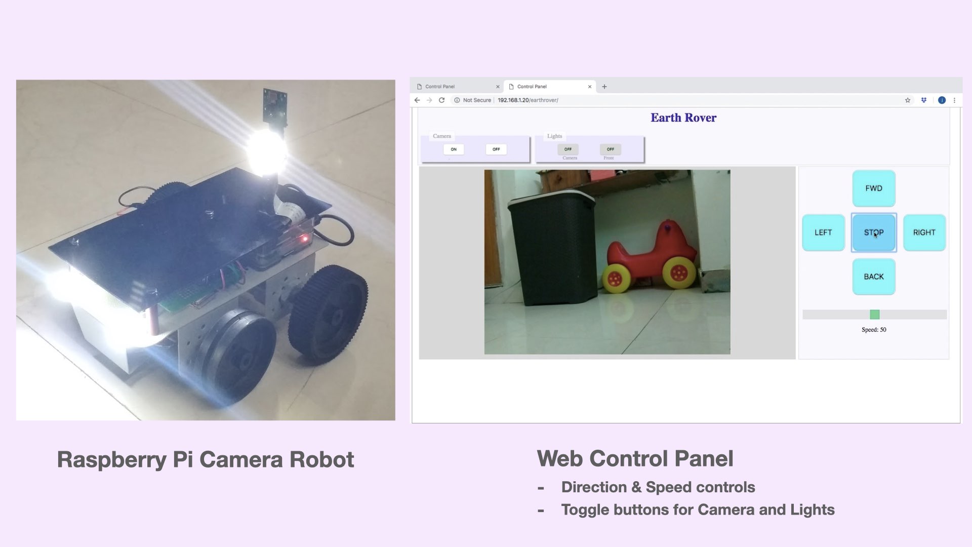
With chassis and motors in place, its time to add some more hardware to our Raspberry Pi robot. To make things interesting, we will create a web based mechanism (Web Control Panel) to control the robot and associated hardware through a browser. This articles covers the details required to build a camera robot capable of streaming real-time video to a remote Web control panel running on a browser of laptop or a smart phone.
Updated for Raspberry Pi OS 13 (Trixie). The code for this robot has been brought up to date with the latest Raspberry Pi OS and now installs with two commands. It also gained a distance sensor that stops the robot before it hits something, a speaker, and support for a USB webcam as well as the Pi Camera. If you built this robot from an earlier version of this article, see the notes marked earlier version below.
Truly remarkable thing about Raspberry Pi is that it can run complex programs just like a PC with modern processor and at the same time it can interact with external hardware through GPIO pins like a microcontroller.
Making use of these capabilities, in this Camera Robot project, Raspberry Pi is has been tasked to perform following:-
- Stream a video (Python script)
- render a Web GUI (PHP, HTML, Javascript)
- Interface with transistor switching circuit for lighting 12 V high brightness LEDs
- Measure distance with an ultrasonic sensor and reverse before a collision
- Speak typed text, and play a horn or a siren, through a speaker
The robot is built using Raspberry Pi 3A+ which has a dedicated port to connect the Pi Camera module. The hardware interfaced with Raspberry Pi in this project is as follows:-
- 12 V LEDs – 03
- Pi Camera – 01 (or any USB webcam)
- BC547 transistors & 100 ohm resistor
- HC-SR04 ultrasonic distance sensor – 01
- Mini speaker for the 3.5 mm audio jack – 01
Hardware connections
The hardware connections covered in previous article have been augmented to cater for additional hardware.Three additional GPIO pins are used in this project to interface Raspberry Pi with Transistor Switching Circuit for lighting 12 V LEDs. Since the GPIO pins of Raspberry Pi work at 3.3 V, they cannot drive 12 V LEDs directly. The Switching Circuit is made using NPN Transistor BC547 and can be interfaced with Raspberry Pi as shown in diagrams below.
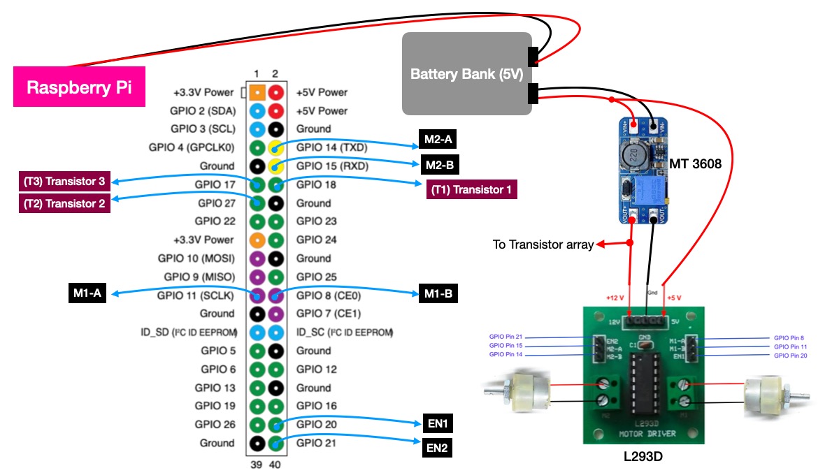
GPIO pins 17,18 and 27 are interfaced with the Transistor Switching Circuit to toggle the 12 V LEDs.
A quick recap of other connections is as follows:-
- GPIO 8,11 & 20 control motor 1.
- GPIO 14,15 & 21 control motor 2.
- A two port battery bank provides power to Raspberry Pi and MT 3608 simultaneously.
- MT 3608 converts the 5 V input supply to 12 V required to run the motors and light up the LEDs.
The distance sensor and the speaker add these:-
- GPIO 23 goes to the TRIG pin of the HC-SR04, and GPIO 24 to its ECHO pin.
- GPIO 9 drives a small LED that blinks while the robot speaks (optional).
- The speaker plugs into the 3.5 mm audio jack of the Raspberry Pi.
The ECHO pin of the HC-SR04 outputs 5 V, while the GPIO pins of Raspberry Pi work at 3.3 V. Put a simple voltage divider (1 k and 2 k ohm resistors) between ECHO and GPIO 24 so the Pi is not exposed to 5 V.
Motor 2 uses GPIO 14, which Raspberry Pi can also use as a serial console. If a motor twitches while the Pi is booting, open /boot/firmware/cmdline.txt and delete the words console=serial0,115200 from the line, leaving the rest of the line as it is.
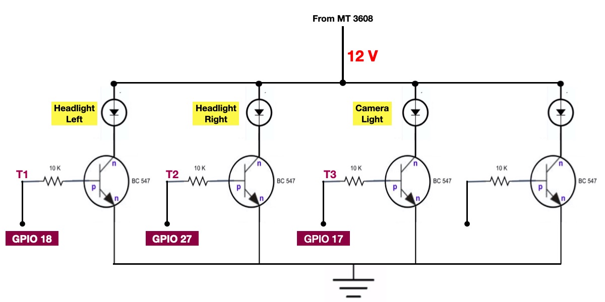
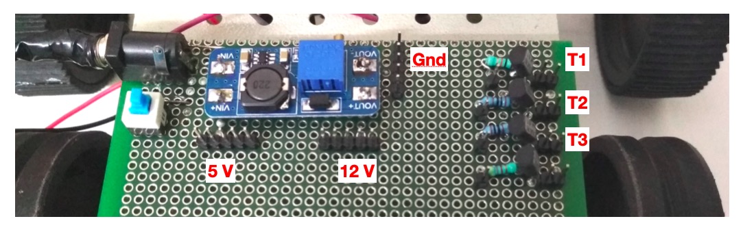
As shown in the diagram above, the base of the transistors is connected to the GPIO pins. By simply making a GPIO pin high or low, we can switch the respective transistor. The actual arrangement of the components on a general purpose PCB is shown below
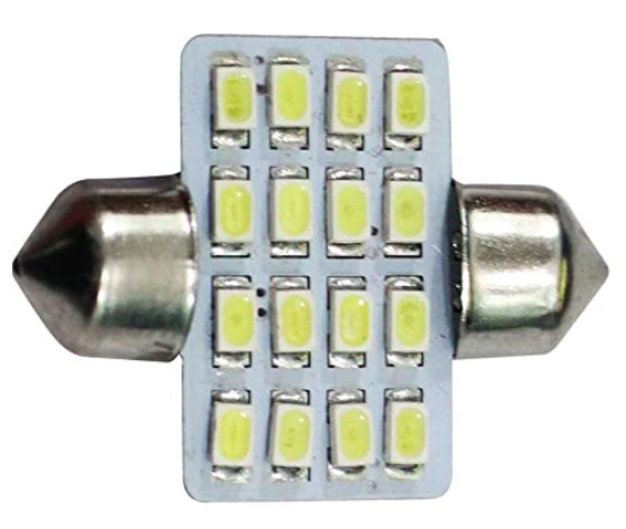
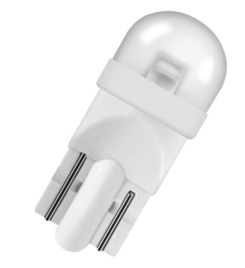
The 12 V high brightness LEDs used in this Camera Robot project are shown below.
|
|
|
Installing the code on your Raspberry Pi
The code has been updated to work with the latest Raspberry Pi OS (Trixie, Debian 13). Two commands install everything — the web server, the GPIO support, the camera and audio tools, and the code itself.
On your Raspberry Pi, download the setup script:
curl -fsSL https://raw.githubusercontent.com/jiteshsaini/robotics-level-2/master/earthrover/setup_level2.sh -o setup_level2.sh
Then run it:
sudo bash setup_level2.sh
Downloading the script first, rather than piping it straight into sudo, lets you read it before running it as root. When it finishes it prints the address to open, http://<your-pi-ip>/earthrover/. Enter that in a browser on your phone or laptop, on the same network as the Pi.
You can run the script again at any time to update to the latest code — it moves your existing copy aside first rather than overwriting it. Level 1 and level 2 install to the same folder, so installing this one moves a level 1 install aside.
What the script does, in case you want to understand the machine you now have, or do it by hand:-
- Installs the web server (Apache and PHP), the Python GPIO library, the camera library, and the speech and audio tools.
- Installs OpenCV, which is what reads a USB webcam.
- Copies the code to /var/www/html/earthrover.
- Lets the web server use the GPIO pins, the camera and the sound card, by adding it to the gpio, video and audio groups.
- Gives it ownership of the few files it has to write — the speed setting, the latest distance reading, the settings file and the log folder.
- Restarts Apache so those changes take effect.
Tested on Raspberry Pi OS Trixie on a Raspberry Pi 3A+.
Testing the connections
Create a blank file, name it ‘test.py’ and copy the following Python code. Run the file using terminal. You should see the LEDs blinking at one second interval.
import RPi.GPIO as GPIO
from time import sleep  # import sleep function from time module

GPIO.setmode(GPIO.BCM)  # choose BCM numbering scheme

GPIO.setup(18, GPIO.OUT)# set GPIO 18 as output pin
GPIO.setup(27, GPIO.OUT)# set GPIO 27 as output pin
GPIO.setup(17, GPIO.OUT)# set GPIO 17 as output pin

while True:
  GPIO.output(18, True)
  GPIO.output(27, True)
  GPIO.output(17, True)

  sleep(1)

  GPIO.output(18, False)
  GPIO.output(27, False)
  GPIO.output(17, False)

  sleep(1)
This code runs unchanged on the latest Raspberry Pi OS. The setup script installs python3-rpi-lgpio, which provides the same RPi.GPIO module and also works on a Raspberry Pi 5. You can also switch the LEDs straight from the terminal, without any code:
pinctrl set 17,18,27 op dh
pinctrl set 17,18,27 op dl
Camera Setup and Testing
The main ingredient of our Camera Robot is the camera. Attach the Pi Camera’s ribbon cable to the camera port of Raspberry Pi, or plug a USB webcam into a USB port — either one works.
On the latest Raspberry Pi OS there is nothing to enable: the Pi Camera is detected on its own when the Pi boots. You can test it from the terminal with the command “rpicam-still -o image.jpg”. Otherwise you can run the following Python code to capture an image.
from picamera2 import Picamera2
from libcamera import Transform
from time import sleep

picam2 = Picamera2()

# hflip and vflip together turn the picture upside down, for an inverted mount
picam2.configure(picam2.create_still_configuration(transform=Transform(hflip=1, vflip=1)))

picam2.start()
sleep(2)
picam2.capture_file("image1.jpg")
picam2.stop()
Earlier version. This section used to ask you to enable the camera in “raspi-config”, test it with “raspistill”, and capture an image with the picamera library. None of these exist on the latest Raspberry Pi OS: the camera no longer needs enabling, “raspistill” became “rpicam-still”, and picamera was replaced by picamera2.
Video Streaming using Pi Camera
The Camera Robot is required to generate a live camera feed which could be monitored through a browser. The original solution came from the advance recipes of the Picamera documentation, which used Python’s built-in http.server module to make a simple video streaming server. The same idea is still at work here, rewritten for the latest Raspberry Pi OS. Once the script is running, the video stream generated by the camera can be accessed by visiting “http://ip-address-of-raspberry-pi:8000" using a browser on a PC or mobile.
The file ‘cam_server.py‘, placed at ‘earthrover > camera_lights’, contains the video streaming Python code. It reads the Pi Camera through picamera2 and a USB webcam through OpenCV, and both feed their frames into the same streaming server, so the rest of the code never needs to know which camera it has. Which camera to use is a setting, chosen from the gear icon on the Web Control Panel:-
if SOURCE in ("auto", "USB_cam"):
    camera = start_usb_cam(output)
    if camera:
        print("camera: USB_cam")

if camera is None and SOURCE in ("auto", "RPI_cam"):
    camera = start_rpi_cam(output)
    print("camera: RPI_cam")

if camera is None:
    raise SystemExit("camera: none available for source '%s'" % SOURCE)
With auto, a USB webcam is used if one is plugged in, and the Pi Camera otherwise. All we need to do is embed the html page “http://ip-address-of-raspberry-pi:8000" in our Web Control Panel and create controls to start and stop the video stream. Next section covers these details.
Web Control Panel of Camera Robot
Web Technologies such as PHP, HTML & Javascript have been used to create the Web Control Panel of our Camera Robot. The code for this project is on Github, and the setup script above installs it together with the web server. The GUI is generated through ‘index.php’ file inside the ‘earthrover > control_panel’ folder, and http://<your-pi-ip>/earthrover/ takes you straight to it.
Observe the various sections of Web Control Panel and the files associated with respective sections. The picture shows the original four sections; the current panel also has a Range Sensor and a Speaker section, covered further below, and gear icons for settings.
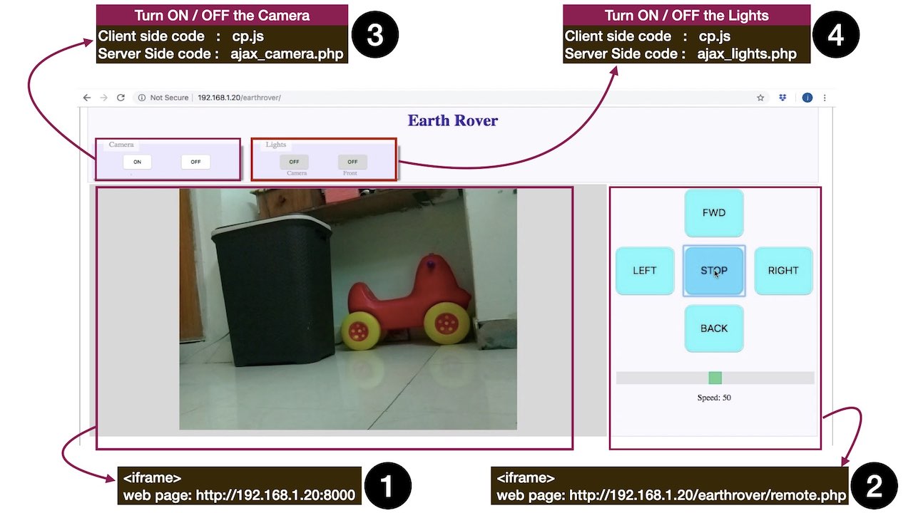
HTML5 provides an easy way to embed a web page inside another web page using <iframe> tag. The sections 1 and 2 are simply embedded in ‘index.php’ file using the following code.
$host=$_SERVER['SERVER_ADDR'];//192.168.1.20
$path=rtrim(dirname($_SERVER["PHP_SELF"]), "/\\"); //earthrover

$link_remote= 'http://'.$host.$path.'/'."remote.php";//http://192.168.1.20/earthrover/remote.php
$link_vid= 'http://'.$host.':8000';//http://192.168.1.20:8000

echo"
	<iframe src='$link_vid' id='box_video'></iframe>
	<iframe src= '$link_remote' id='box_remote'></iframe>
";
Section 1 : Display Video Streaming output of Raspberry Pi Camera
The web page with video streaming output is generated by the file ‘cam_server.py’. As long as this file is running in the background, the video streaming remains available on a web page. This web page is embedded in the Web Control Panel using <iframe> tag as shown in code above.
Section 2: Direction and Speed Controls of Camera Robot
The web page containing the direction and speed controls is served through the file ‘remote.php’. The functionality of this file is covered in previous article. Again, we can simply embed this page in our Control Panel using <iframe> tag as shown in code above.
Section 3: Camera ON/OFF controls
This section has buttons ‘ON’ and ‘OFF’ to control the camera feed. They are created using <input> tag inside ‘index.php’ file using following code. Notice that the ‘onclick’ event of these buttons call the same javascript function ‘camera()’. However, the parameter passed to the function is different. This function is defined in a javascript file ‘cp.js’ placed inside ‘earthrover/control_panel/js’ directory.
echo"<input id='cam_on' type='submit' onclick=camera('on'); value='ON'/>";
echo"<input id='cam_off' type='submit' onclick=camera('off'); value='OFF'/>";
All the javascript on the panel talks to the server through one small helper, ‘post()’, in the file ‘post.js’. Earlier versions of this project loaded the whole jQuery library for this one job; the helper does the same with the browser’s built-in ‘fetch’.
function post(url, data, done)
{
	fetch(url, {method: "POST", body: new URLSearchParams(data)})
		.then(function(r){ return r.text(); })
		.catch(function(e){ console.log("post " + url + " failed:", e); return null; })
		.then(function(text){ if (done) done(text); });
}
The ‘camera()’ function receives parameter ‘on’ or ‘off’ based on the button pressed. It simply passes this value as a POST parameter to a PHP file ‘ajax_camera.php’ in the server, and reloads the page once the server answers. The camera takes a couple of seconds to start, so a spinner shows in the meantime.
function camera(status)
{
		document.getElementById("cam_spin").style.display="inline-block";
		post("../camera_lights/ajax_camera.php", {camera: status}, function(){
			document.getElementById("cam_spin").style.display="none";
			location.reload();
		});
}
The ‘ajax_camera.php’ receives the ‘on’ or ‘off’ value and executes OS command to either launch or kill the Python script ‘cam_server.py’. When starting, it waits until the stream is actually accepting connections on port 8000 before it replies, so the page reloads into a working video frame.
<?php

$cam = $_POST["camera"];

if ($cam == "on") {
	$app = dirname(__DIR__);
	system("cd /tmp && python3 -u " . $app . "/camera_lights/cam_server.py > " . $app . "/logs/camera.log 2>&1 &");

	$ready = false;
	$deadline = time() + 8;
	while (time() < $deadline) {
		$sock = @fsockopen("127.0.0.1", 8000, $errno, $errstr, 1);
		if ($sock) { fclose($sock); $ready = true; break; }
		usleep(200000);
	}

	echo $ready ? "camera: on" : "camera: FAILED to start";
	exit;
}

if ($cam == "off") {
	system("pkill -f cam_server.py");
	echo "camera: off";
	exit;
}

echo "camera: unknown request";
?>
Notice there is no sudo here. On the latest Raspberry Pi OS, the web server can start and stop this script, and use the camera, the GPIO pins and the sound card, simply by being a member of the video, gpio and audio groups. The setup script adds it to them. The web server never gets root access.
Earlier version. This section used to ask you to add www-data ALL=(ALL) NOPASSWD: ALL (and the same line for pi) to the ‘sudoers’ file. That is no longer needed, and it is worth undoing: it lets any web page on the Pi run any command as root. Open the file with sudo visudo and delete those lines.
Section 4: Lights ON/OFF controls
This section also has two buttons. One button can toggle the LED Light of camera and other can toggle the front LED lights of the robot. These buttons are also created using <input> tag inside ‘index.php’ file as shown below. The ‘onclick’ event of these buttons also call a common javascript function ‘toggle_light()’ but with different parameters (id of the button). This function is also defined in a javascript file ‘cp.js’ placed inside ‘earthrover/control_panel/js’ directory.
echo"<input id='camlight' style='background-color:lightgray' type='submit' onclick=toggle_light('camlight'); value='OFF'/>";
echo"<input id='headlight' style='background-color:lightgray' type='submit' onclick=toggle_light('headlight'); value='OFF'/>";
The ‘toggle_light()’ function first toggles the caption & color of the respective button and then calls ‘set_lights()’ function with button id and its desired state as parameters. The ‘set_lights()’ function simply passes these two parameters to a PHP file ‘ajax_lights.php’ in the server, using the same ‘post()’ helper.
function toggle_light(id)
	{
		button_caption=document.getElementById(id).value;
		if(button_caption=="OFF"){
			document.getElementById(id).value="ON";
			document.getElementById(id).style.backgroundColor="#66ff66";
			set_lights(id,1);
		}
		if(button_caption=="ON"){
			document.getElementById(id).value="OFF";
			document.getElementById(id).style.backgroundColor="lightgray";
			set_lights(id,0);
		}

	}
function set_lights(id,state)
{
		post("../camera_lights/ajax_lights.php", {light_id: id, state: state});

}
The ‘ajax_lights.php’ file receives the two parameters (button id and its desired state) via $_POST super global variable. Using these two parameters, it constructs appropriate command to set the corresponding GPIO pins high or low as shown below.
<?php
include_once '../vars.php';

$light_id=$_POST["light_id"];
$state=$_POST["state"];

if ($state=='1') $state='dh';
else $state='dl';

if ($light_id=="camlight"){
	system("pinctrl set $cameralight $state");
}

if ($light_id=="headlight"){
	system("pinctrl set $headlight_right $state");
	system("pinctrl set $headlight_left $state");
}

echo"$light_id, $state";
?>
pinctrl is the tool the latest Raspberry Pi OS provides for setting GPIO pins from the command line: dh drives a pin high and dl drives it low. It only changes a pin that is already an output, so ‘vars.php’ sets all the motor and light pins as outputs (op) every time it is loaded.
Earlier version. The lights used the gpio command, from a library called WiringPi. That library is no longer part of Raspberry Pi OS, so the command does not exist there and the lights would never switch.
Section 5: Range Sensor and collision avoidance
This section has one button that switches the HC-SR04 ultrasonic sensor on and off, and a number that shows the distance to whatever is in front of the robot, in centimetres. While the sensor is on, the robot reverses on its own when something comes closer than the stop distance.
The button calls ‘toggle_rangeSensor()’, defined in ‘rangesensor.js’ inside ‘earthrover/range_sensor/web’. Switching on posts to ‘ajax_rangeSensor.php’ and starts a timer that asks the server for the latest reading twice a second:-
function get_range()
	{
		post(RNG + "ajax_getRange.php", {}, function(data){

			if (data<=30)
				document.getElementById("range").style.color="red";
			else if(data > 30 && data <= 60)
				document.getElementById("range").style.color="orange";
			else
				document.getElementById("range").style.color="blue";

			if (data>400)
				document.getElementById("range").innerHTML = "-";
			else
				document.getElementById("range").innerHTML = data;

		});
	}
‘ajax_rangeSensor.php’ runs ‘master.py’, which starts three Python scripts in the background: ‘range_sensor.py’ takes the readings, ‘monitorSensor.py’ restarts it if it stops, and ‘avoid_collision.py’ moves the robot. Switching off stops all three.
os.system("python3 -u " + local_path + "/range_sensor.py" + LOG)
time.sleep(1) #should be equal to settling time of range sensor
os.system("python3 -u " + local_path + "/monitorSensor.py" + LOG)
time.sleep(0.1)
os.system("python3 -u " + local_path + "/avoid_collision.py" + LOG)
The HC-SR04 measures distance with sound. A 10 microsecond pulse on the TRIG pin makes it send out an ultrasonic burst; the ECHO pin then stays high for as long as the sound takes to bounce back. Sound travels at about 34300 cm per second and the pulse covers the distance twice, so the distance in centimetres is the pulse duration multiplied by 17150. ‘range_sensor.py’ does this four times a second and writes the result to a file, ‘range.txt’:-
GPIO.output(TRIG, True)
time.sleep(0.00001)
GPIO.output(TRIG, False)

# wait for the echo pulse to start
timeout_at = time.time() + ECHO_RISE_TIMEOUT
while GPIO.input(ECHO)==0 and time.time() < timeout_at:
	pass
if GPIO.input(ECHO)==0:
	print("No echo pulse - sensor not responding (check wiring/power)")
	time.sleep(0.25)
	continue
pulse_start = time.time()

# wait for it to end
timeout_at = time.time() + ECHO_FALL_TIMEOUT
while GPIO.input(ECHO)==1 and time.time() < timeout_at:
	pass
pulse_end = time.time()

pulse_duration = pulse_end - pulse_start

distance = pulse_duration * 17150
The two timeouts matter. Without them, a sensor that is unplugged or wired wrongly leaves the script waiting forever for a pulse that never comes. When nothing is within the sensor’s 400 cm range, the script writes 999 instead, and the panel shows “-“.
‘avoid_collision.py’ reads the same file in a loop. When the distance is less than the stop distance, it reverses the robot for one second, says “obstacle detected”, and stops. The stop distance is read on every loop, so a change made from the panel applies at once:-
while 1:

	f1 = open(local_path+"/web/range.txt", "r+")
	distance = f1.read(20);
	f1.close()

	if (distance=="" or distance=="--"):
		time.sleep(0.2)
		continue

	#read every loop, so a change from the web UI applies without a restart
	if(float(distance) < ut.setting("distance", 30)):
		ut.back()
		ut.speak_tts("obstacle detected","f")
		time.sleep(1)
		ut.stop()

	time.sleep(0.2)
Section 6: Speaker
This section lets the robot talk. Type a sentence in the box, choose a male (M) or female (F) voice, and press ‘speak’. The ‘horn’ and ‘siren’ buttons play a recorded sound. Any speaker or pair of headphones plugged into the 3.5 mm jack works.
The ‘speak’ button calls ‘button_tts()’ in ‘speaker.js’, which sends the text and the voice to ‘ajax_tts.php’. That file starts the Python script ‘speaker_tts.py’ in the background:-
$text   = escapeshellarg($text);
$gender = escapeshellarg(preg_match('/^[mf]$/', $gender) ? $gender : 'm');

$APP = dirname(dirname(__DIR__));
$cmd = "cd /tmp && python3 " . $APP . "/speaker/speaker_tts.py " .
       $text . " " . $gender . " > " . $APP . "/logs/speaker.log 2>&1 &";

system($cmd);
The text typed on a web page ends up inside a command run on the Pi, so it is passed through ‘escapeshellarg()’ first. Without it, a sentence containing a quote or a semicolon could run a command of its own.
‘speaker_tts.py’ turns the text into speech with espeak-ng and plays it with aplay. On a Raspberry Pi the default sound output is HDMI, which a robot has nothing plugged into, so the script sends the sound to the 3.5 mm jack by name:-
def alsa_device():
    try:
        with open("/proc/asound/cards") as f:
            if "Headphones" in f.read():
                return " -D plughw:CARD=Headphones,DEV=0"
    except OSError:
        pass
    return ""

cmd_speak = (TTS + " -ven-us+" + gender + "5 -s120 " + "'" + text + "'" +
             " --stdout |aplay" + alsa_device())

os.system(cmd_speak)
The ‘horn’ and ‘siren’ buttons post the name of a sound file to ‘ajax_omx.php’, which plays it with mpv. Only mp3 files from the robot’s own ‘sounds’ folder are accepted:-
$req  = basename($_POST["rec_path"] ?? "");
$file = $SOUND_DIR . "/" . $req;

if ($req === "" || !is_file($file) || pathinfo($file, PATHINFO_EXTENSION) !== "mp3") {
	http_response_code(400);
	echo "unknown sound";
	exit;
}
Earlier version. The robot used espeak and omxplayer. Both have been removed from Raspberry Pi OS; espeak-ng and mpv replace them.
Section 7: Settings
The gear icons on the Camera and Range Sensor sections open a small settings box. The Camera gear chooses which camera to use and which way up its picture should be — each camera keeps its own orientation, because a Pi Camera and a USB webcam are rarely mounted the same way up. The Range Sensor gear sets the stop distance.
The settings are saved in a plain text file, ‘config.txt’, in the install folder, and you can edit that file directly if you prefer:-
camera=auto                 # auto | USB_cam | RPI_cam
flip_RPI_cam=rotate_180     # none | rotate_180 | horizontal_flip | vertical_flip
flip_USB_cam=none           # the same four, for the USB webcam
distance=30                 # centimetres; the robot reverses closer than this
The file is written by ‘ajax_settings.php’. Because the scripts that drive the hardware read this file, it only accepts the settings and values it knows:-
$ALLOWED = array(
	"camera"        => "/^(auto|USB_cam|RPI_cam)$/",
	"flip_RPI_cam"  => "/^(none|rotate_180|horizontal_flip|vertical_flip)$/",
	"flip_USB_cam"  => "/^(none|rotate_180|horizontal_flip|vertical_flip)$/",
	"distance"      => "/^[0-9]{1,3}$/",
);
Hopefully, the details covered in this article are adequate to build a simple Web Controlled Camera Robot. The README on Github lists every file in the project and what it does.
Hello
The picamera is replaced by libcamera and it seems like the camera is not responding. I don’t know if I’m the only one experiencing the unresponsiveness of the camera due to the upgrade. Is there any way to make it functional again?
Yes. The support for Picamera has been removed from Raspberry Pi OS. As of now, the project can be run on previous OS (buster).. which can be downloaded from here
https://downloads.raspberrypi.org/raspios_armhf/images/raspios_armhf-2021-05-28/
hello, good day, is there any update about the camera? I encounter a recent problem while tinkering with your project. The camera is not responding but before it works well. I’ve searched through the internet and it says that there are recent development about the camera and it was now on libcamera. I’m newbie and I don’t really know what to do or what to change. please help.
good day sir, I try to use the package version and I’m trying to remove the AI robotics but everytime I remove the code for that, the camera will no longer function. why is that sir? I’m removing that features because it’s does not give accurate results, I think its on my camera or maybe some kind of interference on my part. Now I only want to use the camera for surveillance and other features, I hope you can help me sir and also, thank you, it was a great project of yours.
Hi,
Great job indeed!
How would software change in case of USB camera?
Thanx
You need a different python script to use a USB cam. You can install OpenCV and use any USB camera or Picamera.
Hello
Does this and rest of earthrover project need the led lights to work,
Will it conflict with the codes of the project or is it safe to only add the cameras from this section of the project and continue the work.
You can continue without led lights. Code won’t conflict. Only camera will work just fine.
Do you supply the parts used in making these projects or else do you make projects on demand.
I don’t supply parts. I buy them online. I won’t be able to spare time for making projects on demand. But I can guide you.